TL;DR I presented this work at Insomni’hack, if you’d prefer to watch the recording of that then you can find it here: https://www.youtube.com/watch?v=Nvw_BH7jPzE
Imagine you’re on a physical engagement, standing outside an office door. You need an access card but you don’t have one (yet). You notice that there’s a pattern where employees need to tag in, but to leave they just wave their hand and the door swings open. You pull a torch out of your backpack and switch it on. There’s no visible light but a subtle vibration assures you that it’s on and working. You shine it through the glass door, pointing it at a bookshelf, a chair or wall on the inside, like trying to line up a shot in pool. Within about 5 seconds… pop! The door swings open, there’s nobody else in sight and you walk right in. Not even a fingerprint left behind. It turns out, this scenario isn’t as farfetched as you might think.
A very good place to start
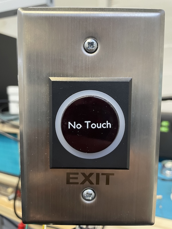
Let’s go back to the very beginning. This all started when I noticed a certain type of sensor being used for access control. A cheap-looking device with the words “no touch” across the front, opening doors when you waved your hand in front of them. In all honesty, the first experiments were centred around whether they responded differently to different skin tones (they don’t), but the lunchtime science experiments got me thinking – how strong are these controls really? In this case, they were used to allow people to exit areas which required some kind of access control to enter: an RFID fob or fingerprint, but leaving the area just required a hand wave. Fair enough, you shouldn’t need credentials to “log out”. What interested me was the range: they seemed to pick up a hand wave from about 5-10 cm away depending on the sensor. It was clear that they were using infrared (IR) to accomplish this based on the telltale colour of the lens (deep red and translucent), and the fact that it would be the cheapest, most reliable way to do what they were doing. Infrared is a common method of distance sensing. What if we could somehow trigger them from the other side of the door and let ourselves in from the outside?
Given that they were easily available, and cheap, the next step was to buy one. I found one on a local e-commerce site for R350 (around $20) and a few days later it was in my hands. Time to open it up! Given that access control tech is generally quite expensive and this was… not, the inside was more or less what you’d expect from a device made to be as cheap as possible.

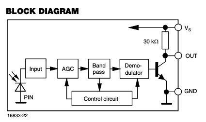
Tracing the connections revealed a few main components and their functions:
- An IR emitting LED
- An IR receiver
- An adjustment knob at the back that changes the brightness of the emitting LED
- 8 LEDs (blue and green) to signal a trigger (these light up a ring around the sensor)
- A relay to control something, usually a door lock
- A controller that ties it all together
This was a pretty good result overall. The controller was easy to stick a clip onto for watching the signals which was the next step: switch it on and see what’s actually happening.
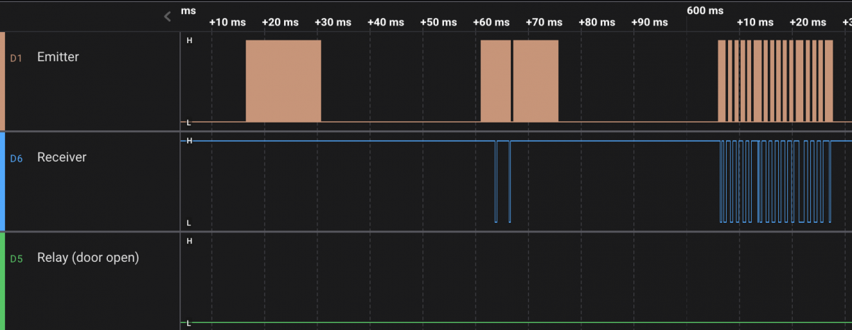
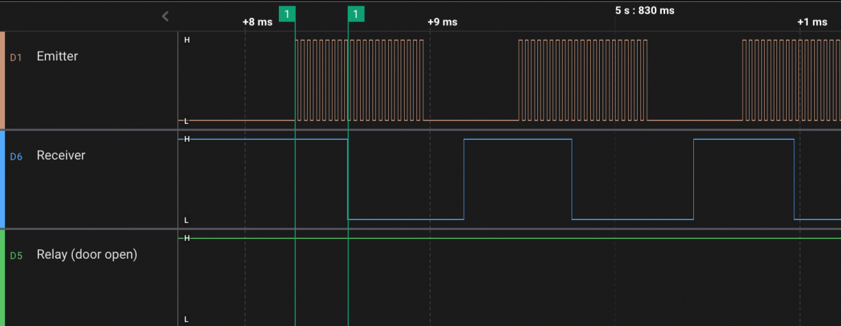
This is a logic analyser trace of the unit powered up and operating as normal. The lines are the signal levels (high/low, analogous to binary 1 and 0 in the digital realm) of each leg on the chip over time. Some legs are just for power or aren’t used so they aren’t shown here.
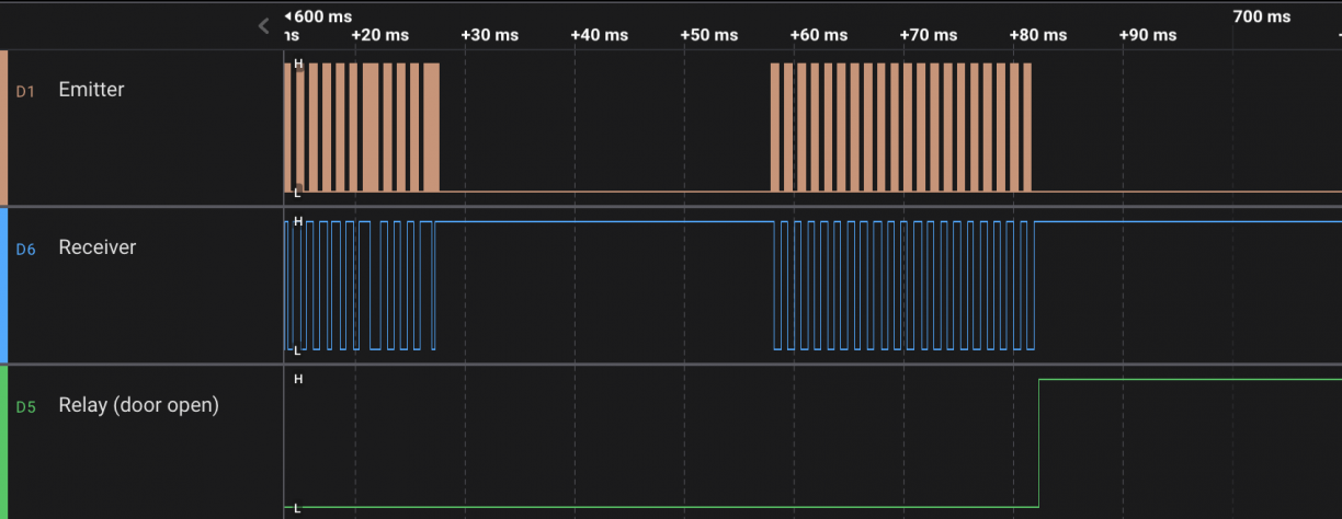
The repeating signal at the top is what’s being sent to the emitting LED. The next signal shows what happens when an object comes close to the switch. First with quite a bit of loss, but steadily improving, the emitted signal is reflected and the device detects it. Despite the emitter and receiver being right next to each other, there’s a plastic shroud in between preventing them from interacting directly. The signal will only be received if something reflects it back to the device from a fairly narrow angle. As my hand gets closer, the received signal becomes more and more representative of the emitted signal until… pop! The third signal shows the relay being triggered and the theoretical door now opens.
You might have already noticed, I said that the second signal was representative of the first, but beyond the timing, they don’t actually look the same. This is because there’s a lot more going on in that IR receiver than you may think. Near-infrared (the specific range we’re dealing with) occurs naturally, there’s a bunch of it coming from the sun and indoor lights, so relying on the presence of energy at that wavelength isn’t going to be reliable. Something that doesn’t occur naturally is a high-frequency toggling of that energy – known as a carrier signal. This is why the first signal in the trace looks like a solid block, it’s actually a high-speed signal.
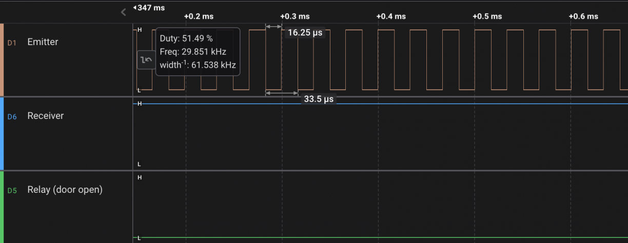
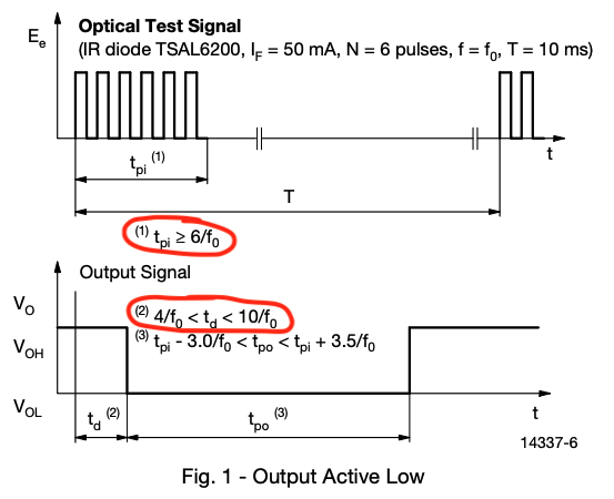
The receiver has an internal filter that only responds when it detects this carrier, and an amplifier to boost the resultant signal. Carrier present equals signal high, carrier absent means signal low. It’s a surprisingly reliable system and it’s exactly what’s used in nearly every TV and air conditioning unit remote control made in the last few decades. Of course, the carrier signal needs to be present for a little while before the signal can assert high, and the time needed can vary depending on a variety of factors. The datasheet states that anything between 4 and 10 pulses are needed before the signal will assert high. This is great news for us because it means that there needs to be some tolerance in what the device will accept as a “representative” signal.
The plan
The theory is that if we can introduce a signal that looks enough like the one the device is expecting, then it will detect a “reflection” and trigger the relay (open the door). We know exactly what the signal looks like, and getting the timing close but not perfect means that our signal will drift in and out of sync of the real signal, hopefully triggering a detection in the process. Something that works in our favour here is that the IR receiver module is highly sensitive and will pick up the smallest signal – the range is determined by how brightly the emitter is shining and how reflective the surface is. If we introduce our own light source, we do away with the loss of the reflection and we can make it as powerful as we like!
I removed the emitting LED entirely and set up a test jig to loosely generate the signal we’d captured; this way I’d know that if there was a trigger, I’d have caused it. I genuinely expected this to work first time, but to my disappointment, nothing. Looking at the traces, I realised that something weird was going on: my signal drifted in phase with the emitted signal like I’d expected, and it was detected, but as soon as it was detected, the emitted signal changed completely.
A faux impasse
At this point I thought it might be the end of this experiment. A change in signal looked to me like tamper detection and reacting to it meant knowing when you were in sync with the actual signal, a much harder problem to solve. I was immediately discouraged. I shelved the project for a while and focused on other stuff and it turned out to be an important lesson, I’d jumped to the conclusion about what was happening and the theory of how to bypass it was suddenly quite overwhelming. The mistake I made here, was that my assumption was wrong. This hurdle I’d just encountered was almost entirely of my own making, but it was enough to stop all progress because of the perceived difficulty. Research, in general, is just as much proving that things work in a certain way as it is disproving. Hurdles do appear and they can slow or even stop progress, but it’s not a hurdle until you’ve done your due diligence to prove that it is one and this was my mistake – something I try to keep in mind when exploring new avenues of attack.
Take two
At some point in the wasted time since I last played with this device, I had a really dumb idea: When I sent the observed signal, it changed. The door would likely open if the secondary signal was received at that point, so what if we just do away with the first signal and emit the second signal from the start? This was a simple enough theory to test, so I did, and it worked! Unreliably at first, but tweaking the length of the bursts that the signal was transmitted for made it more effective. Transmitting the signal continuously caused the device to stop responding until we stopped transmitting, possibly detecting our signal as interference, so the burst approach was the most effective. This was a working attack!
Gimme range!
These experiments took place in my office, so range was pretty limited. Tests were done with a small infrared LED about a metre away from the sensor. The intention was to prove that the concept worked before trying to make it a practical attack in the field. So naturally, we needed more power. I had a super powerful infrared LED and lens in my parts box, so I 3D printed a little holder for the LED, the lens and a microcontroller to generate the signal and mounted it on a tripod.

Initial tests with this setup were extremely successful and I was able to trigger the sensor from about 6 m away. This was a great result and meant that this attack was possible, if we could see the sensor. Unfortunately, most sensors are installed facing the person leaving the area, not the person trying to enter. At best, they’re on the wall next to the door, but the shroud to stop the sensor from detecting itself limits the angle of attack to about 30 degrees at best. Luckily, we’re in control of the signal now. All we need is more power :)
Between increased power and a lens, we could get a pretty nicely focused beam at a decent range. Going back to how the device is supposed to work, a hand is sufficient to reflect the extremely weak emitted signal. So if we have a significantly stronger light source, we should be able to reflect that as well. For example, against a wall. While this would depend on having a surface behind the sensor and being close enough to bounce off it, this already makes our chance of success far greater in a real-world scenario.
The torch
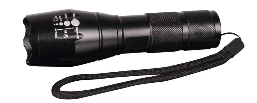
Now that we’d proven the concept, the next step was to shift this into a form factor that was usable in the field. If we want to show impact, we’re going to need to break into something and bringing a tripod into an office park is not the answer. Since the goal is to build a portable device that shines a powerful light through a lens, the perfect device already exists: a torch! Torches don’t typically shine infrared, nor do they modulate the light in the way that we want, but these are small changes to an already inconspicuous and near-perfect form factor. A few torches were tested, the main requirement was that it had space somewhere inside where we could sneak some extra components and that the LED could be replaced with an IR one. The model I settled on was the “Gorilla Lightforce Ultra Torch” which was a local rebrand of a fairly inexpensive torch. What was interesting is that I bought one of the cheaper no-brand torches and while they looked identical, they had less space inside and were generally more cheaply made. This particular torch was perfect because a replacement IR LED was easy to source, it had plenty of space inside, it could accommodate AAA batteries or an 18650 lithium cell, and it had a telescopic zoom function – perfect for ranged attacks!
The initial prototype was a dead-bug1 style circuit with a fair amount of tape to keep it all together. It really should have given me more issues, but it just worked. This allowed testing in the field and it worked like a dream, as long as there was line-of-sight to the sensor, or a surface nearby that I could bounce it off. The telescopic zoom meant that I could put a nice bright spot on a wall behind the sensor and it usually needed no more than about 10 seconds to get the alignment right and open the door. In this field testing, I discovered 3 issues:
- Since you can’t see IR light, you can’t tell where you’re aiming
- Again, because it’s IR, you can’t even tell whether it’s on or off
- Some sensors didn’t respond, even at point-blank range, even though they looked identical to the ones in testing.
For the aiming, there were some thoughts around attaching a laser to the torch to assist. This was tricky as there was no easy way to mount it. In the end, with a bit of practice it got easier and the aim assist was abandoned in favour of a less suspicious looking device (and accidentally putting red laser dots on people’s heads). As for knowing whether it was on, a small vibration motor was added so that you could feel if it was on. This was perfect as only the holder knew it was happening so it didn’t draw attention like a visual or audible indicator might have. For the last problem, the firmware now cycles through 3 different patterns for different sensors. I’ve come across 2 sensor types which I haven’t been able to trigger with an external signal, but with enough time it should be possible to trigger these as well.
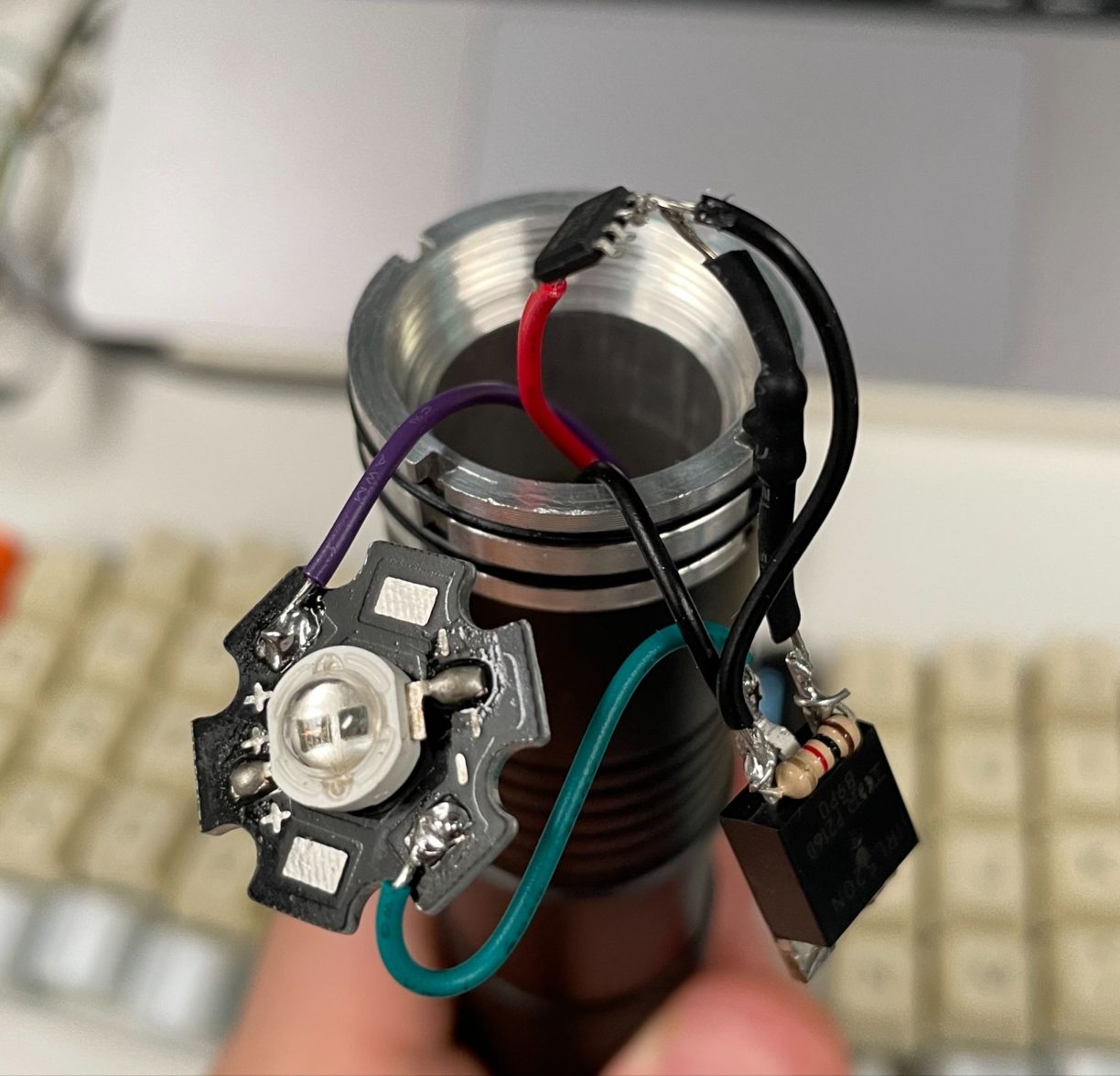
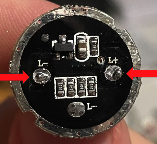
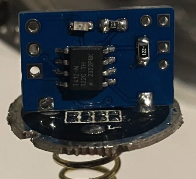
To wrap it all up, the nasty dead-bug circuit (now proven in the field) was converted into a neat little PCB which could be soldered onto the torch’s original PCB. The torch’s original controller was removed and the board remained to provide power and a place for our new controller to live. It contains an ATtiny412 microcontroller, a MOSFET for driving the high-power LED, and a small visual LED to see whether it’s on during testing (not visible from the outside). There was lots of space for this and the vibration motor in the head of the torch.
How do we fix this?
This is a bit of a tricky problem. If this were a software issue, it would be easy enough to contact the vendor and report it. All going well, a patch is rolled out and the problem slowly solves itself. With hardware, it’s not so easy. It’s already deployed in the field and can’t be easily patched. To make it worse, this is not a single device, but a whole device type that has been produced by a number of manufacturers and sold around the world under hundreds of different brands. If there’s a vulnerability in teaspoons, who do you contact? Sure, these devices aren’t as pervasive as teaspoons, but you get the idea.
The more effective approach in this case is to raise awareness amongst implementers, and as penetration testers, that’s exactly what we’re called to do. I don’t foresee criminals running around with crime torches breaking into buildings, but it’s important to understand the potential risks when installing “budget” devices as critical components of your physical defences. Hopefully, through awareness, we’ll see less and less use of these devices in this way. The takeaway is that no-touch sensors shouldn’t be used for security purposes, only convenience. They shouldn’t replace physical locks and where physical access is required to activate something, stick with a good old button.
 ︎
︎